Create Your First Project
Start adding your projects to your portfolio. Click on "Manage Projects" to get started


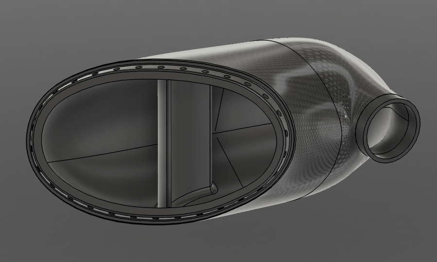
VLX 600 Intake Manifold
Date
June 2025 - Present
Location
Fitchburg MA, Binghamton NY
I am in the process of converting a Honda VLX 600 motorcycle from its original carbureted fuel system to electronic fuel injection. One of the most challenging components to design and manufacture is the new intake manifold. Early in my research I discovered that the geometry of the manifold can be tuned so that it actually boosts the engine’s performance at certain rpm ranges. This effect arises from two related acoustic phenomena: quarter-wave or “organ-pipe” tuning, and Helmholtz resonance. I am designing the manifold to take advantage of both of these to enhance performance at a specific rpm band.
Because this is my first serious experience in designing a fluid system, I have spent a great deal of time gathering technical sources, textbooks, and papers on acoustic wave tuning and intake manifold dynamics until I felt confident that the geometry I am designing will achieve the desired effects. Once I had numbers for the runner length and plenum volume that seemed reasonable when compared to the intake manifold for similar rpm and engine sides, I made a first pass at the geometry and stuck the fluid region into Ansys Fluent.
To establish a baseline and help validate the simulations, I designed and built an Arduino-based data-acquisition system that uses a differential-pressure sensor together with an inexpensive inductive tachometer. This setup lets me measure the differential pressure across the current intake system versus engine rpm at wide-open throttle. These measurements give me a picture of how the stock manifold behaves.
At first, I ran just a steady state simulation, and when my computer reported back colorful lines that looked like they were going in the right direction, I began a transient simulation. Using the maximum differential pressure values from my DAQ, I wrote a MATLAB program that would generate an ideal profile of the pressures at the outlets as I knew the valve timing, maximum vacuum pressure and angle between the cylinders of my four-stroke engine over two intake events for each cylinder. I used this data to plot the mass flow rate at the outlets.
I found that the air inside the plenum was very turbulent and poorly distributed between the outlets. There was about a 12.7% disparity between the mass flow rate to the front and rear cylinders. I added a vane in the center of the plenum to direct flow more evenly between runners. After many hours of simulations and many design iterations, I was able to get the disparity down to 2.17%. This seemed good enough and by this time I was starting to dream of path lines, so began finalizing my design.
After showing my design to the technicians at the fabrication lab at my school, they pointed out mistakes made by previous formula SAE teams and suggested that a completely 3d printed intake manifold could break and fill my engine with hot melted plastic. Since I am a broke college student and cannot afford a new motorcycle or fully metal 3d printed parts, I decided to design the plenum to be 3d printed out of glass filled SLS Nylon 12 wrapped in carbon fiber. This still allows me to have un-machinable geometry that makes Ansys happy, while fitting in the tiny envelope above my front cylinder. I also selected fuel injectors and finalized the runner design.
I am confident that my intake will do what it was designed to do, I now need to order a bunch of sensors and ensure that they will fit nicely into the 3d print and not mess up all the work I have put into this up until this point.
If this is interesting to you or I irreparably goofed something up please do feel free to reach out!